BAUDI/O
BAUDI/O

This post is a bit lengthy and focuses more on the journey behind creating the device rather than the technical details. If you’re more interested in the technical specs, head over to Github to read the documentation and download the Gerbers to build one yourself. Hopefully, you’ll find the background story intriguing…
Background
My fascination with audio electronics began when I discovered the CMoy DIY headphone amplifier. The thrill of hearing music from something I built was incredible and addictive. Over the years, I crafted numerous power and headphone amplifiers, fueled by my passion for the audio and DIY audio subreddits. One project I always wanted to revisit was that first headphone amplifier, but with a twist: using SMD components to see how small I could make it. However, staring at the PCB, I realized how uninspiring it was and never printed it.
A few years ago, the trend of creating business card-sized PCBs with functional circuits caught my eye. Inspired, I decided to fit the CMoy amplifier onto a business card, which was quite straightforward due to its minimal components.
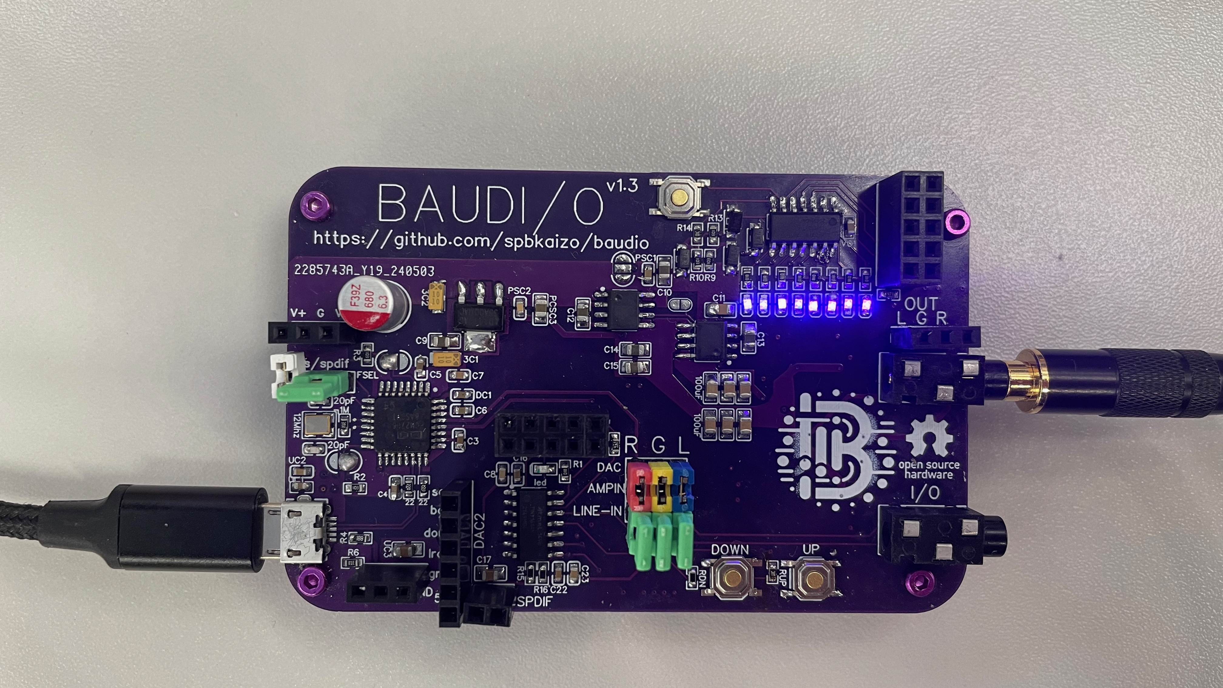
Naturally, the amp needed power, so I added a micro USB connector. Then I thought, “Why not include a DAC to kill two birds with one stone?” So I did. From there, I added power components, needed 3.3V for the DAC, and thought, “Why not expose that power supply for other projects?” And so it went, with each cool idea leading to the final product you see in the photo.
With about 160 components, building the board isn’t a quick project. But I hope you try to build one, and I promise to support any issues raised on the GitHub page!
How does it Sound?
I think it sounds pretty awesome - but I’d love for others to build one and tell me how I’m wrong! My ears sadly aren’t what they once were!
What’s on it?
It’s hard to pinpoint where to start because this device serves multiple purposes. At its core, it’s a headphone amplifier, but it’s also a DAC, an Arduino-like toy for digital audio, and a way to play with the new AVR-1 chips. Let’s start with the power supply.
Power Supply
Designed for easy audio experiments, it includes a +/-5V dual power supply and a 3.3V supply for other boards or breadboards. You can breadboard a CMoy amplifier and power it with this device, avoiding virtual grounds or other complexities.
DAC
It’s a PCM2706C dac, which exposes the ability to shift via a jumper between SPDIF and I2S functionality - you can use this breakout to play with other DACS, as a lot of 3rd party boards don’t expose USB connectivity but do expose I2S connectivity.
You can also use SPDIF to light up and LED, and marvel at another device consuming that digital audio.
Or you can just hook all this up to a scope and look at real audio digital data signals.
CMoy
Although it started as a CMoy, the design evolved. The first op-amp follows the classic arrangement, but the output goes through a Sallen-Key filter to a secondary op-amp in unity-gain mode for more power. You can experiment with the filter, gain, and different op-amps here.
Volume Control
Initially, I considered an Alps potentiometer but opted for an I2C digital pot controlled by an ATTiny1614. With spare pins exposed via another breakout, you can experiment with light-dependent volume control, wave your hand over an LDR to mute, and more. Sample code is in the repo, perfect for learning avr-libc and C programming.
VU-Meter
Another ATTiny1614 controls 8 LEDs connected to the L/R channels, allowing you to tinker with ADCs on the ATTiny.
Learnings
This project has been a fantastic learning journey. From realizing the need to DC bias analog signals before they enter the digipot, debugging USB high-speed signals, optimizing traces, designing a 4-layer PCB, to overcoming other challenges, I’ve enjoyed every moment and the process of solving problems.