Sony Portable CD - The D-EJ2000 and EU Volume Limiting
Sony Portable CD - The D-EJ2000 and EU Volume Limiting
I bought a few years ago what is considered one of the best examples of Sony engineering - a D-EJ2000. Unfortunately, this model if you got it in the EU comes with a rather silly limiter on the output to stop us europeans going deaf.
This limits it by a factor of 10, to 0.6mw output compared to 6mw of output for the ’tourist’ version or the US version.
I’ve been trying to track down the changes for sometime, and I’d scoured the service manual trying to find any differences. Then the other day, as I came across it in a drawer, I figured I’d give it another shot.
I managed to find a newer version of the service manual which had the magic secret components listed in it.
Closely looking at the datasheet, and with ChatGPT giving me a secondary assessment also, the magic components that I think need changing are as follows.
Lineout
- R313 - The manual states “For models EXCEPT AEP, EE, UK: 100kΩ”
- R314 - As above, for the other channel.
Interestingly, these are on the line-output stage. R313 and R314 appear to be part of a resistive network in the line-out signal path. Changing their values will directly impact the amplitude (voltage level) of the signal reaching the line out.
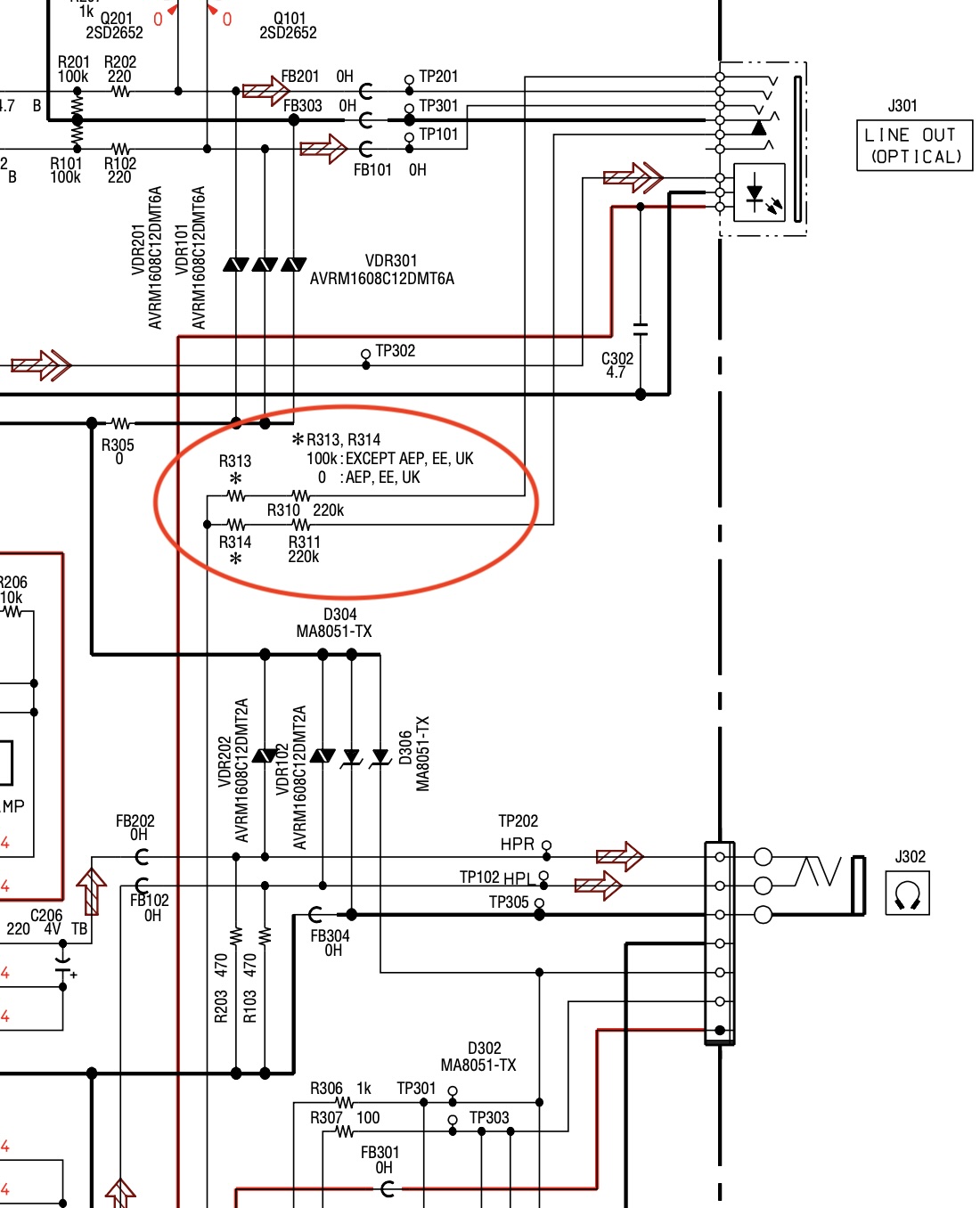
Keep reading, we need to come back to this as it’s important!
Currently, for European models (AEP, EE, UK), R313 and R314 are short-circuited (0Ω), meaning they have no effect on the signal. For other models, they have a combined resistance of 200kΩ (100kΩ each). I’m rather confused by this arrangement, I would have assumed the lineout voltage to be ‘standard’ across both models.
I’ve measured a 1kHz sinewave on the line out at 0.363v, or 363mV. Normally, decent line-out is in the region of 2.00v, for example from a mains powered CD player. You’d be exceptionally hard pressed to find anything which outputs beyond 2.10v. Keep this in mind as we continue. Read to the bottom!
Headphone out
There’s another 2 differences, which are actually going to affect the output voltages.
I’m going to take a guess that once these are changed, the lineout voltage will increase also by a factor of 10, giving us the 6mW we are after versus the 0.6mW we actually got.
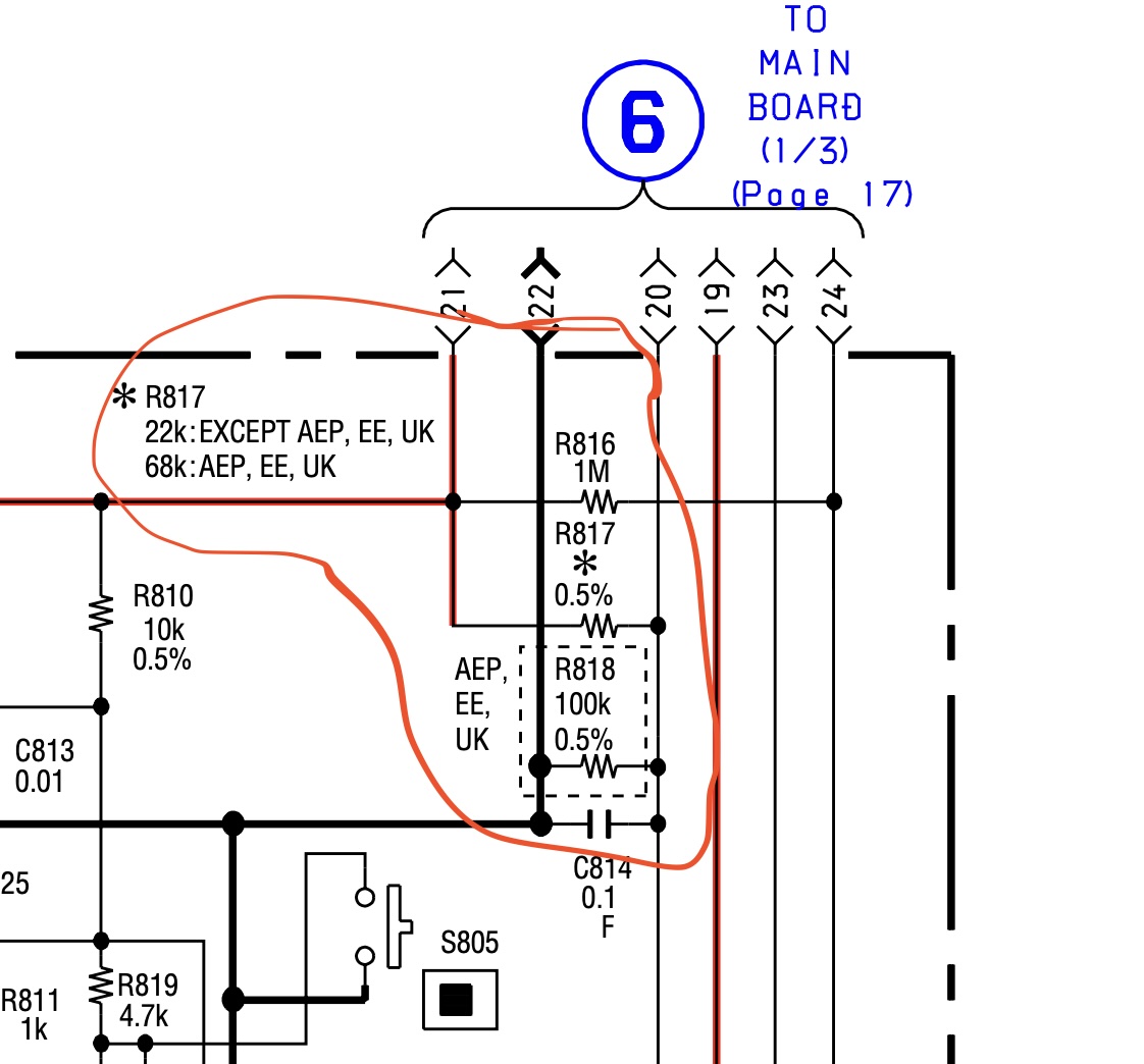
- R817 - Change from 68kΩ (European models) to 22kΩ (other models)
- To achieve an overall resistance of 22kΩ by adding a resistor in parallel to the existing 68kΩ resistor, you would need to add a resistor of approximately 32.52kΩ
- The closest standard values are typically 33kΩ or 32kΩ
- I was originally thinking of trying to piggy back on top of the existing resistor - but now I think the best course of action is to remove it and replace it.
- R818 - This is a 100k resistor, which only appears on the EU model
- It needs removing
- DO NOT JUMPER IT
So, where are these resistors located? Well, looking at the service manual, R313 and R314 are located near pin 60/61 of IC801 (square 80 pin IC). This IC is the middle IC on the board (you should see 3 square IC’s on this side), so easy to find. Find the marker dot for pin 1, and head down to the next corner!
The other two, R817 and R818 are located to the south-east of IC602, a 26 legged chip in a rectangular configuration. Flip the board over, With the jog dial at the top, and the board in a C shape, they’re just south of the sled motor CN602.
Current Output
Padon the pun, as we’re measuring AC voltage out here. Playing a 1Khz wave I measure 0.084v, or a rather poor 84mV.
If we assume some 16 ohms headphones, then we’re getting about 0.000441W delivered to them - in other scales, 0.441 mW. This was at top volume output, though I’m not 100% sure the test file was at 0 dBFS. Regardless, this is pretty much the correct ballpark for what was expected.
Plugging the values into an SPL calculation for my iSK Studio HD9999 headphones, with 32 ohm resistance and 96dB sensitivity, we can reach the lofty heights on a 1Khz sinewave of……89.43 dB. This is all rather poor.
I have a pair of ToneKing T400S’, epic earphones with amazing sensitivity of 112dB. These will output higher, at 94.46 dB - a full 5dB !
The non-EU version has 10x more power, so assuming all the same calculations we’ll end up with the following:
- The iSK Studio HD9999 would produce a sound pressure level (SPL) of approximately 109.43 dB
- The ToneKing TO400s would produce an SPL of approximately 114.47 dB
Much better!
I don’t normally listen to music higher than around 80 dB, so in theory I should be fine ‘as it is’, but I’d much rather have the ability to go load. Also, and I’ve not studied the diagram enough, a lot of audio equipment performs much better with a lot of headroom.
Lineout - A Warning!
I’m rather glad you got this far, as perhaps the most important information I have is here.
Remember that lineout, where we europeans had a 0 ohm resistor on the lineout, but everyone else had a 100k? Well guess what - if we’ve bumped up the output on the headphones - we’ve also bumped up the output power on the lineout - probably higher than 3.64v! Equipment go boom if you plug it in.
It would be prudent to make sure you add the 100k resistors to this output - even if you think you will never connect it - as one day you may sell the player or someone finds it, and the input stage on their amp goes into overdrive…
Soldering
Well, good luck. The resistors are 0402 sized I think, i.e. they are precisely 1mm long by 0.5mm wide.
You will need to have some flux, and a decent iron.
Here’s some photos I’ve managed to take.
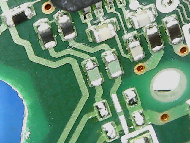
lineout
The two in the middle link up to what appears to be a bridged set of pads - though it may be a jumper.
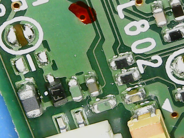
Gain Override
The one to the right of the diode named f7 needs removing, and the one south of it in the photo needs replacing.
Oh, and that’s not actually blood. Was there when I found it…
Final Results
Well it’s not an easy task - these resistors are crazy small.
The unit is now considerably more powerful - anything above 3/4’s of the max volume on the bar is what I would consider too loud, which is the exact outcome I was hoping for. The original volume limited configuration I could happily ‘burst’ to full volume without it being overly loud.
| Before V | Before mW | After V | After mW | |
|---|---|---|---|---|
| Headphones Out (16 ohm) | 0.084v / 84mV | 0.441mW | 0.461v / 461mv | 13.282mW |
| Line Out | 0.363v / 363mV | 0.713v / 713mv |
Right, time to go find my high impedance cans…